|
Hall’s Liliput Bank — Part 2
(Types I, II, III)
by Sy Schreckinger – ANTIQUE TOY WORLD Magazine – September, 2008
“Hall’s Liliput”, the mechanical bank selected
to be subject of this article, is one that is often perceived as
insignificant and lackluster. At first glance, it may compare unfavorably
to its "flashier" and more animated brethren. Closer inspection, however,
reveals a mechanical possessing elegance and dignity contained within its
simple design.
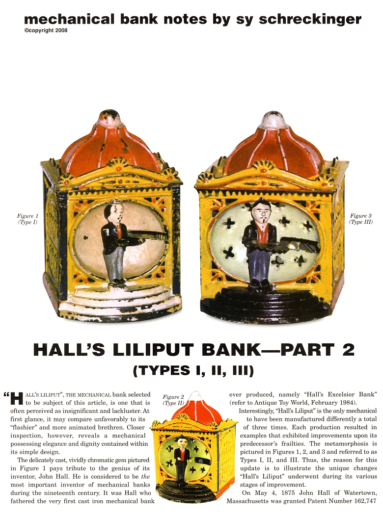
The delicately cast, vividly chromatic gem pictured in Figure 1 pays
tribute to the genius of its inventor, John Hall. He is considered to be
the most important inventor of mechanical banks during the nineteenth
century. It was Hall who fathered the very first cast iron mechanical bank
ever produced, namely "Hall's Excelsior Bank" (refer to Antique Toy World,
February 1984).
Interestingly, "Hall's Liliput" is the only mechanical to have been
manufactured differently a total of three times. Each production resulted
in examples that exhibited improvements upon its predecessor's frailties.
The metamorphosis is pictured in Figures 1, 2, and 3 and referred to as
Types I, II, and III. Thus, the reason for this update is to illustrate
the unique changes "Hall's Liliput" underwent during its various stages of
improvement.
On May 4, 1875 John Hall of Watertown, Massachusetts was granted
Patent Number
162,747 HALL'S LILIPUT", THE MECHANICAL bank selected to be
subject of this article, is one that is (Figure 4) for his "Liliput Bank".
The J. and E. Stevens Company of Cromwell, Connecticut subsequently
manufactured Hall's creation. However, as evidenced by the final
production bank, Figure 1, the Stevens Company did not adhere to these
patent drawings.
On July 27, 1875 "Design" Patent Number
8,498 (Figure 5) was issued
to John Hall. This patent is of considerable interest since it
incorporated an actual photograph of the "Liliput Bank" rather than the
customary drawing, implying the bank's design was patented after it was
manufactured. The words "PATENTED MAY 1875", "JAN 1876" "PAT DESIGN, JULY
27, 1875" cast into the sides and back of the bank facilitated location of
the patent papers.
A unique feature indicative of all mechanical banks designed by John
Hall was the usage of a coin's weight to initiate action. Yet, on April
24, 1877, Hall was granted a patent for an "improvement" on his "Liliput
Bank" (Figure 6). It utilized a lever which, when pressed, resulted in the
commencement of action with or without usage of a coin. To the best of my
knowledge this lever design was never incorporated into any manufactured "Liliput
Bank". (If there is any reader who does have knowledge of such a 'lever
activated' "Hall's Liliput Bank", such information would be greatly
appreciated.)
Figure 1 represents the earliest of "Liliput" banks (Type 1). It not only
displayed a much narrower facade then its successors but also demonstrated
a conspicuous manufacturing defect resulting in the redesigned and
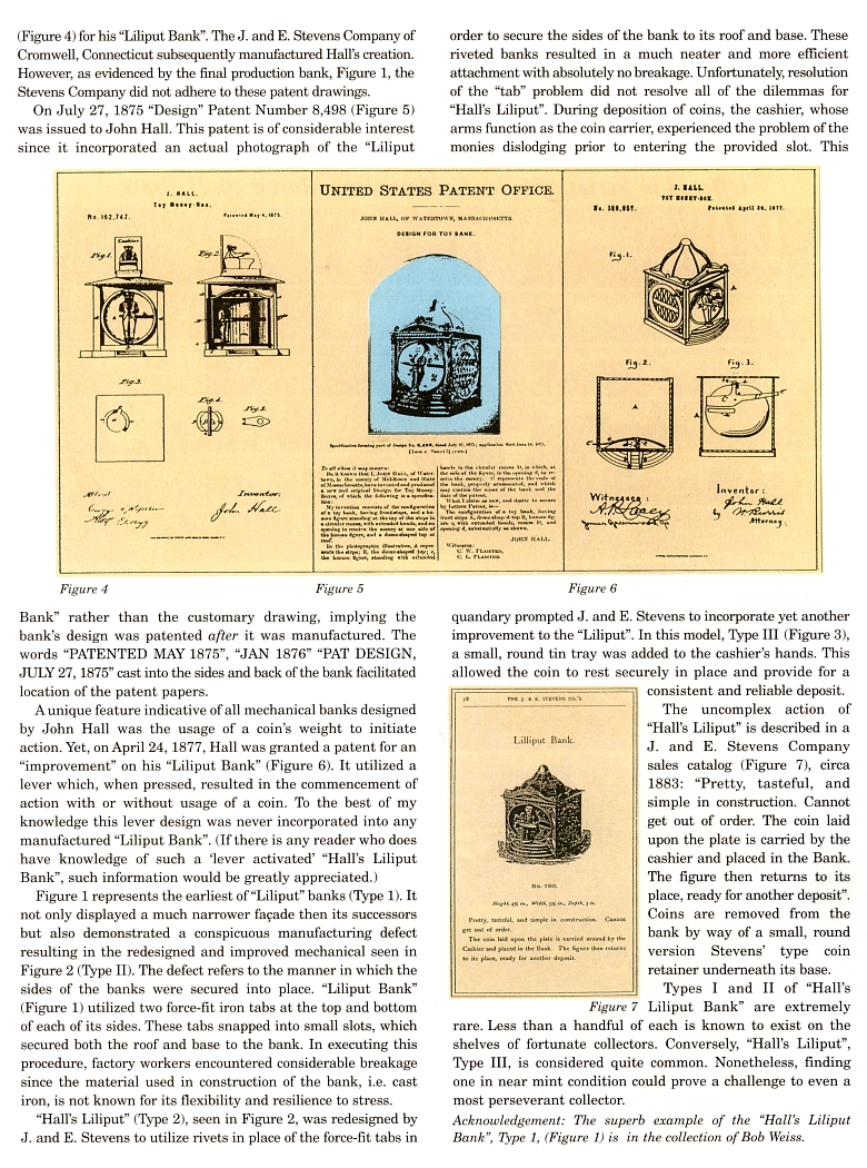
improved mechanical seen in Figure 2 (Type II). The defect refers to the
manner in which the sides of the banks were secured into place. "Liliput
Bank" (Figure 1) utilized two force-fit iron tabs at the top and bottom of
each of its sides. These tabs snapped into small slots, which secured both
the roof and base to the bank. In executing this procedure, factory
workers encountered considerable breakage since the material used in
construction of the bank, i.e. cast iron, is not known for its flexibility
and resilience to stress.
"Hall's Liliput" (Type 2), seen in Figure 2, was
redesigned by J. and E. Stevens to utilize rivets in place of the
force-fit tabs in order to secure the sides of the bank to its roof and
base. These riveted banks resulted in a much neater and more efficient
attachment with absolutely no breakage. Unfortunately, resolution of the
"tab" problem did not resolve all of the dilemmas for "Hall's Liliput".
During deposition of coins, the cashier, whose arms function as the coin
carrier, experienced the problem of the monies dislodging prior to
entering the provided slot. This quandary prompted J. and E. Stevens to
incorporate yet another improvement to the "Liliput". In this model, Type
III (Figure 3), a small, round tin tray was added to the cashier's hands.
This allowed the coin to rest securely in place and provide for a
consistent and reliable deposit.
The uncomplex action of "Hall's Liliput" is described in a J. and E.
Stevens Company sales catalog (Figure 7), circa 1883: "Pretty, tasteful,
and simple in construction. Cannot get out of order. The coin laid upon
the plate is carried by the cashier and placed in the Bank. The figure
then returns to its place, ready for another deposit". Coins are removed
from the bank by way of a small, round version Stevens' type coin retainer
underneath its base.
Types I and II of "Hall's Liliput Bank" are extremely rare. Less than
a handful of each is known to exist on the shelves of fortunate
collectors. Conversely, "Hall's Liliput", Type III, is considered quite
common. Nonetheless, finding one in near mint condition could prove a
challenge to even a most perseverant collector.
Acknowledgement: The superb example of the "Hall's Liliput Bank",
Type 1, (Figure 1) is in the collection of Bob Weiss.
|