|
To
all whom it may concern:
Be
it known that I, JAMES H. BOWEN, a citizen of the United States,
residing in the city and county of Philadelphia, State of Pennsylvania,
have invented a new and useful Improvement in Toys, which improvement is
fully set forth in the following specification and accompanying
drawings.
My invention consists
of a toy embodying a figure having a head which may be turned from side
to side and legs simulating the motions of walking, the figure also
rising and falling.
It also consists of
means for imparting motion to the toy, as will be hereinafter fully set
forth.
It also consists of
other novel features, as will be described and claimed.
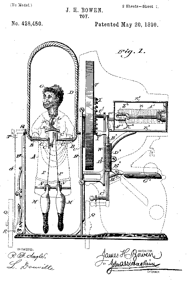
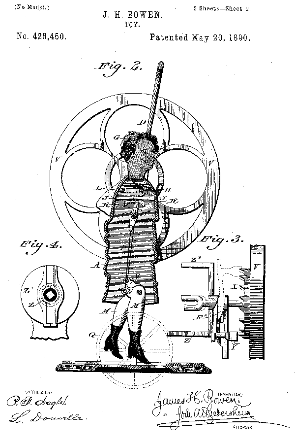
Figure 1 represents a
front view of the toy embodying my invention. Fig. 2 represents a
vertical section thereof. Fig. 3 represents a side elevation of n
detached portion, Fig. 4 represents an end view of a detached portion.
Similar letters of
reference indicate corresponding parts in the several figures.
Referring to the
drawings, A designates a figure formed of suitable metal or other
material, in the hands B of which is journaled a crank-shaft C, whose
ends are connected with a bow or bow-shaped piece D. Projecting from the
sides of the bow D near the ends of the shaft C are journals E, which
are mounted on the uprights F, so that as said shaft C is rotated rising
or falling motions are imparted to the figure.
G designates the head
of the figure, whose neck is connected with a vertical crank-shaft H,
the latter being mounted on cross-pieces J within the body of the figure
and having secured to its lower end an arm K, which is located above the
central cranks C' of the shaft C and
so disposed that said cranks may successively strike the ends of
the the arm K, thus vibrating the latter and rotating the head and
causing it to turn to the right and left. In order to return the head to
its normal position, there is secured to the frame or body of the figure
and the crank of the shaft H a spring L, the operation of which is
evident.
M designates the leg's
of the figure, the same being pivoted to the lower end of the body of
the figure and formed with limbs N at their upper ends, forming
elbow-levers or cranks, to the upper ends whereof are connected the
wires or rods P, which are hung on the cranks C' of the shaft C. By this
provision the leg's are moved in imitation of walking, the rods P being
alternately raised and lowered by the cranks C', the motions of which
are communicated to the legs. The uprights F maybe supported on wheels
Q, the shaft whereof carries a crank R, to which is attached a
connecting-rod S'. The upper end thereof is attached to a crank T,
continuous on one of the journals E on the side of the bow D, by which
provision the shaft C receives motion, the effect of which is to cause
the turning or swaying of the head of the figure, the movement of the
legs, and the ascent and descent of the figure, as has been stated, said
wheels Q, cranks R and T, and connecting-rod S' being shown in dotted
lines, Fig. 1.
For the purposes of a
money-box, motion is imparted to the shaft C by means of a
friction-wheel U, which engages with a shaft U', of the power-wheel V,
said shaft U' being mounted on a frame W. On the side of the wheel V is
a ratchet X, with which engages a dog or detent Y, the latter being
connected with a crank-shaft Z, which is mounted on a frame Z'.
Encircling said shaft Z is a coiled spring A', one end of which is
connected with the frame Z' and the other end with a fork K-2 on the
shaft Z, said shaft being also squared for the application of a key by
which the spring may be wound.
B'
designates a sliding latch, the upper end whereof is adapted to engage
with a lip or projection on the detent Y, the lower end having a handle
C-2, so that the latch may be conveniently lowered, and thereby released
of the holding-contact with the detent, said latch being raised and held
in its normal position by a spring D', which is suitably connected with
said latch and the guide E', in which the latch is fitted. The portion
of the crank of the shaft Z which is adjacent to the detent Y is adapted
to move in a cam-passage or bear against a cam F', which is formed on
the inner end of the frame Z', it being noticed that when the shaft C is
rotated in one direction and the spring A' wound up the detent Y, moving
in the cam-passage F', is advanced toward the ratchet X, and when it has
fully described its motion and forced down the latch B' it then engages
with said latch, so as to be locked by the same, and it furthermore
engages with one of the teeth of the ratchet X, Pivoted to the guide E'
is a tray G' for receiving coin, it being noticed that the several parts
enumerated, beginning with the friction-wheel U, are enclosed in the
box, (shown in dotted lines, Fig, 1,) said box being adapted to receive
money or coin. Projecting from the side of the portion of the latch B'
below the guide E' is a foot H', which bears against |
the under side
of the tray G', near the axis
thereof, so as to hold the same in horizontal position, it being seen
that when a piece of coin is inserted through a slot in the box so as to
be dropped upon the tray G' the latch B' is lowered by the handle C', a
portion of which is outside of the money-box,
whereby the detent Y is released, and as the spring A' now controls said
detent the power of the spring is communicated to the ratchet, and
consequently to the power-wheel V, and thus motion is transmitted to the
crank-shaft C, whereby the figure is rotated in a manner similar to that
herein before described, As the detent described its rotary motion and
plays in the cam-passage F', its nose is gradually withdrawn from the
engaging tooth of the ratchet X and removed from the path of the
ratchet, so that the power-wheel rotates without obstruction on the part
of the detent, as will be seen in Fig. 3. It will also be seen that as
the latch B' is lowered the foot H' follows the same, and thus the tray
G' loses its support and drops, whereby the coin is deposited in the
box, as illustrated in Fig, 1. The latch B' then returns to its normal
position and again elevates the tray, after which the shaft may be
rotated, whereby the detent engages with either tooth of the ratchet and
is locked by the latch.
The
bow D simulates a jumping-rope, and is constructed of metal in imitation
of the twisted strands of a rope, the ends of the bow being connected
with the shaft C, so that when the said shaft is operated the bow is
rotated, this part of the toy when in operation producing an imitation
of a child jumping rope.
Should
the bow D be obstructed or stopped, it will not to any material extent
interfere with or injure the features of the toy or gearing thereof, as
the friction-wheel U is permitted to slip on the shaft U', the rotation
of the wheel V continuing as long as its momentum endures.
Having
thus described my invention, what I claim as new, and desire to secure
by Letters Patent, is-
1.
A toy having a rotatable crank-shaft, a figure having hands loosely
fitted on said shaft, a bow connected with the ends of said shaft, legs
pivoted to the lower part of said figure and having angular limbs, and
rods connected with crank-arms on said crank-shaft and upper limbs of
the legs, said parts being combined substantially as described.
2.
A toy having a rotatable crank-shaft, with a bow connected with its
ends, and a figure with movable head and legs, and having hands loosely
fitted on said shaft, said head having depending parts adapted to be
engaged by the crank-arm of the shaft, and the said legs having rods
connecting the angular limbs thereof with crank-arms on the said
crank-shaft, said parts being combined substantially as described.
3.
A toy having a figure with hands, a shaft with cranks and journaled in
said hands, a bow secured to the ends of said shaft, a head with
vertical crank-shaft having bearings in said figure and carrying an arm
the ends of which are adapted to be in contact with the cranks of the
shaft, pivoted legs with limbs forming elbow-levers, and rods connecting
said limbs with the said cranks of the shaft, said parts being combined
substantially as described.
4.
A toy having a rotatable shaft with a figure freely mounted thereon, a
bow rigidly connected with said shaft, a second shaft in frictional
contact with a wheel on the first-mentioned shaft, a wheel connected
with a ratchet-wheel on the second shaft, and a spring actuated pawl
adapted to contact with said ratchet-wheel and thereby rotate the same,
said parts being combined substantially as described.
5.
A toy having a rotatable shaft with a figure freely mounted thereon, a
bow connected with said shaft, a second shaft in frictional contact with
a wheel on the first shaft, a ratchet-wheel on the second shaft, a frame
with a shaft having a coiled spring thereon, and a pawl on the end of
said shaft and adapted to contact with said ratchet-wheel and thereby
rotate the same, said parts being combined substantially as described.
6.
A toy having a spring and a shaft actuated by the same, and a latch for
rendering said spring inactive, in combination with a tray or pan which
is held in operative position by means of a foot or projection on said
latch, substantially as described.
7.
In a toy, a rotatable crank-shaft with a figure freely mounted thereon,
a bow secured to said shaft, mechanism, substantially as described,
connected with said Shaft for rotating the same, and pivoted angular
limbs having their upper ends connected by rods with said crank-shaft,
said figure having a turning head provided with arms adapted to be moved
by said crank-arms, said parts being combined substantially as
described.
JAMES H. BOWEN
Witnesses:
JOHN A. WIEDERSHEIM,
A. P. JENNINGS |


